Modeling Common Aspects of Organization
The aim of the unified knowledge base is to document different aspects of the organization in one place and in the unified format. This means that the knowledge base may include a wide variety of information, each requiring a different documentation approach.
1. Business Modeling
This section shows how to model the business aspects of the organization.
Organization Modeling
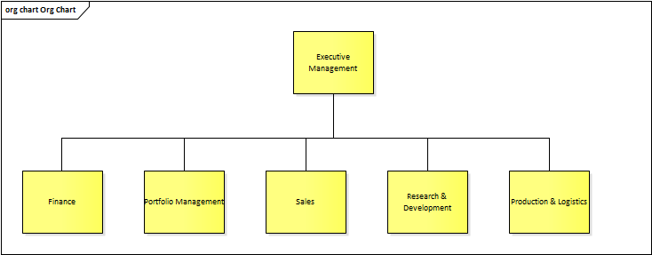
Documenting organizational structure may seem to be marginal, but the opposite is true. From the analysis perspective, knowing how the organization is structured is vital for three reasons:
- Analysts need to know who are the decision-makers to discuss the problem and the solution with the right people
- Analysts must understand whom the new solution will impact most, so that the most important parties are involved
- The solution itself can mean a change to the organizational structure, so analyst must be able to present the change by comparing the current state and the future state
Enterprise Architect offers a specialized model for organization modeling under Strategic Modeling -> Org Chart:
Glossary
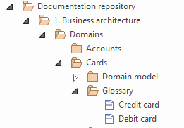
Each industry uses specific terms that describe its business domain. Similarly, each organization speaks its own language. The glossary of these terms is an essential part of the knowledge base:
But what are the reasons to store the terms in the repository as objects, when they basically represent just textual definitions?
- They could be organized, structured and searched in the repository
- The object representation allows for reusing
- Although most terms will be simple textual statements, some will require a comprehensive description with advanced formatting, tables, images or links
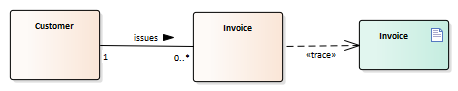
- Many terms will also represent domain entities and to avoid duplication, it should be possible to trace the entities to the respective terms
Business Rules
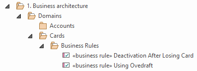
Reasons for storing business rules as objects in the repository are basically the same as for the glossary, so please refer to the previous point for details. The following examples are included to illustrate why reusing business rules and referencing them from diagrams is especially important:
- It is very common that multiple systems operating in the same domain are controlled by the same business rules. For this reason, the list of rules must be company-wide, not tied to any system or project:
- Since business rules control the operation of the whole company, it is common that the same business rules are used to model multiple aspects. As a result, they must be referenced from the models, not included:
2. Process Modeling
From the perspective of processes, the following two principles must be achievable by the CASE tool: Multiple Views and Avoid Duplication. The former represents the need to describe various process levels, the latter is the general requirement for reusing elements in process diagrams.
Process Levels
A process model is usually not a single diagram. In most cases, it is needed to look at the process from the different perspectives, so except for the very simple processes, understanding the process thoroughly requires analyst to draw multiple models at various levels of detail.
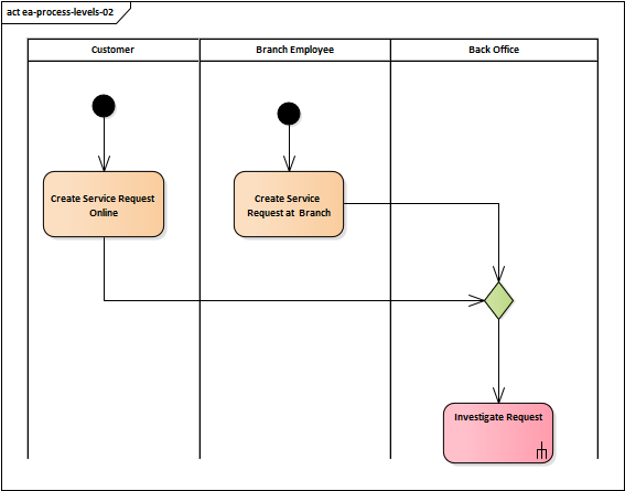
In the L0 process diagram below, the Investigate Request is not atomic and its behaviour is encapsulated inside the element.
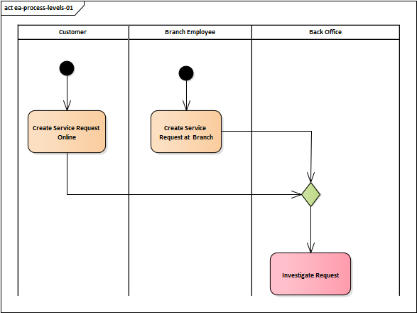
In order to enable the principle of Coherence and Traceability, it must be possible to easily navigate to the inner behaviour. In case of processes, the behaviour is mostly represented by an acitivity:
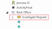
The easiest way to make the activity a behaviour of the process step is to drag it into the diagram as an invocation:
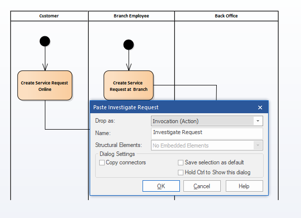
Now it is possible to navigate to the diagram describing the step Investigate Request by double clicking the respective element.
Instance Classifiers
The aim of process modeling is to capture steps (what) that are performed to achieve some goal and in which order (when) they are performed. But to describe the whole picture, analysts also need to know often who performs the step and in which system. Both can be effectively solved with swimlanes.
Using swimlanes in diagrams is straightforward. What is not so clear, though, is what the swimlanes should represent. Analysts often do not know the official role names or the organizational structure, so the common practice is they name the swimlanes as they heard it from the stakeholders. And because different stakeholders call the roles differently, we can see HR Manager, HR Team Leader or Head of HR to be used in the single specification, which is confusing and makes the outputs hard to read. It is ok in the early project stages when analysts are not yet seasoned, but sooner or later, it must be clear who exactly (role, department, etc.) will be performing the given task. To make it crystal clear and to prevent duplication, the recommended way is to map the swimlane to the concrete party, for example, to the organizational structure:
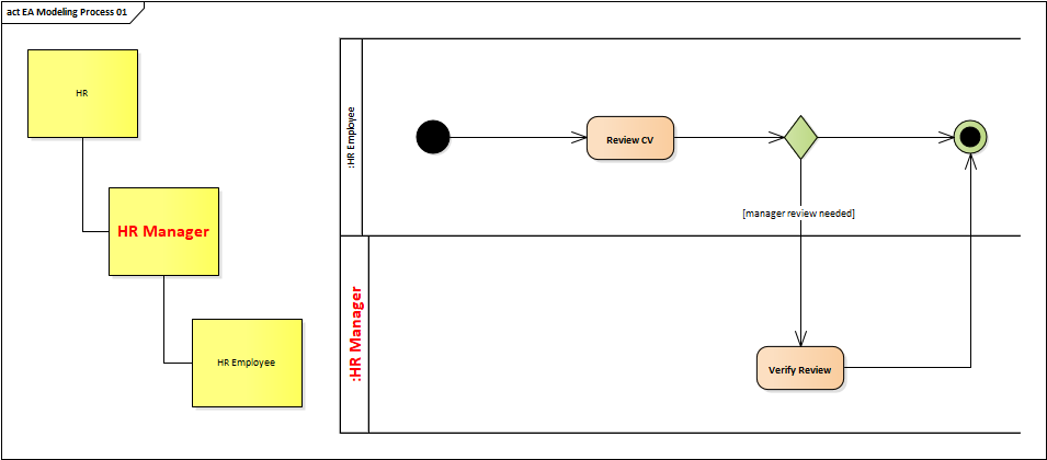
Note: Although a UML Activity Diagram is used for modeling the examples, the tips presented in this section apply to other notations as well.
There is a very convenient way to do the mapping in Enterprise Architect, called Instance Classifier (context menu -> Advanced->Instance Classifier...). It allows to state that the element represents (is an instance of) some "type". For example, in the diagram above, the swimlane :HR Manager is an instance of the object HR Manager, which represents the role of the HR Manager in the organizational structure. This way, the swimlane is mapped to the object, so including the HR Manager in multiple diagrams does not introduce duplication. Besides, renaming the HR Manager role to HR Team Leader in one place will be automatically propagated to all diagrams.
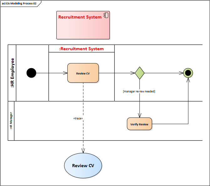
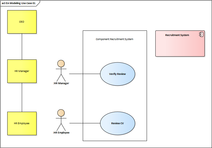
Documenting which system is used to perform the step is done exactly the same way. If the element representing the system is included in the documentation, setting it as the swimlane instance classifier does exactly what is needed.
In the following example, the step Review CV is executed by HR Employee in the Recruitment System:
3. Requirements Modeling
Note: This section does not address the issue of whether to manage particular requirements as repository objects or not (see this chapter for details). It only outlines approach how to manage in Enterprise Architect those requirements which the team did decide to manage as objects.
Enterprise Architect has a built-in element called Requirement. If the elements are stored as elements, each requirement is identifiable and can be assigned attributes such as a priority, difficulty, rationale, and so on. They can also be traced to other artifacts and exported as data items.
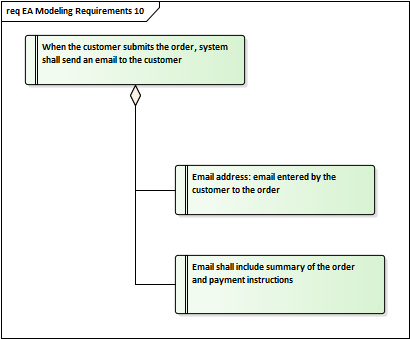
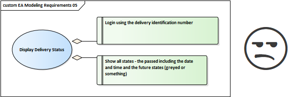
The following example represents the typical requirement which is stored as Requirement element:
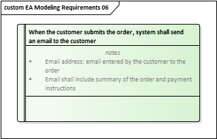
On closer inspection, it becomes clear that it is actually a group of requirements - another two requirements are included in the attached note. If the situation requires to store also the child requirements as standalone elements, it may be solved like this:
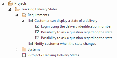
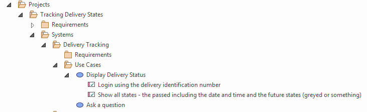
Although the approach which connects the child requirements with their parent using aggregation is quite common, we personally do not prefer it. It requires creating a diagram that has no additional value, and creating the relationships themselves is time-consuming. Instead, we advise to organize requirements in a tree structure which reflects more the natural decomposition of the requirements and does not require to create unnecessary requirement diagrams:
Use Cases
The aim of the use case modeling is to describe what the user wants to do with the system. It is hence important to clearly state, who is the user (actor) and what system is being modeled (system boundary). Mapping actors to roles and system boundaries to applications is the same operation as mapping the swimlanes using instance classifiers as it was introduced the section dedicated to process modeling:
Scenario
A scenario is the core component of the use case and represents the reason why the use cases were actually invented. And these two facts are why we do not use the EA's build-in use case scenarios writing tool:
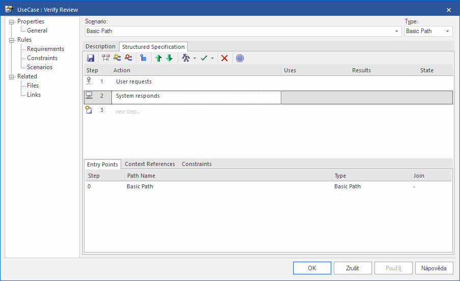
It looks very cool at first sight. It is easy to put down the steps of the scenario, the steps are marked with the "actor" and "system" icon visualizing the user-system "ping-pong", it supports alternate and exceptional flows, and the scenario can be exported to a document. What it lacks, though, are the advanced editing features and ability to complement the steps with additional information.
The scenario is a backbone of the use case and each step represents a hub of related information, such as requirements, user interface details, business rules, or implementation artifacts like functions or services. This requires the use case step to be more than just a plain text statement. Analysts need advanced text formatting, possibility to include attachments, and the possibility to insert images or hyperlinks. They also need to be able to add notes and comments to the scenario steps or to create substeps.
All these issues are easy to solve if the use case is stored in the repository and its specification is generated as a wiki page.
Functional Requirements
Functional requirements are no different from other types of requirements regarding modeling in Enterprise Architect, so they can be represented by the Requirement element. However, since there can be hundreds of them, they are often captured in the form of notes attached to the artifact, which they specify. If some of them are to be stored as standalone elements, it is recommended to store them nested under the related artifact:
4. System Modeling
While Enterprise Architect is not the best tool for documenting business aspects of the organization, it excels in modeling various aspects of the system.
In this chapter, we will walk through the typical system components and will show how to best describe them in EA.
System Overview
Besides the textual overview of the system, it is also convenient to have a visual representation of how the system fits into the environment and how it interacts with it. This is best done using a context diagram, which is basically just the most high-level data flow diagram: Data Flow Diagrams -> Data Flow in EA.
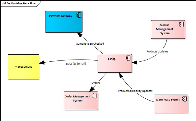
Note: Different colors indicate whether the components are internal or external.
This diagram shows interactions between the system and other entities, be it other systems or organizational units. For example, the Eshop system regularly sends statistics to Management via email. The context diagram describes the logical flows which do not necessarily need to be mapped to a particular artifact. The aim is to explain what goes in and what goes out in a language that is understandable for everybody. It could include the information that the data flow is realized by the data file DTA-13F, but it would be too concrete for this purpose and level of detail.
System Components
Complex enterprise systems aggregate functions from various domains, and to reduce the complexity, they are usually broken down into multiple modules. For example, a typical Customer Management System (CRM) includes modules such as Accounts, Leads, or Opportunities.
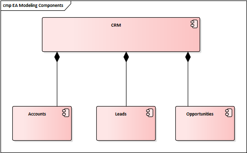
Modules are not standalone applications, they represent logical parts of the system, and the reason why they exist is to decompose the system into smaller parts that are easier to handle. Modules are connected with the parent system using composition or association and can be further decomposed into submodules.
System Integration
A context diagram provides a handy overview of the high-level data flows between the system and the external entities. It is advantageous to get the basic idea of how the system interacts with the environment, but from the system documentation’s point of view, it is not sufficient. To really understand how the system works, it is necessary to document also the lower-level interactions, such as the real service calls and the actual data being exchanged.
I) Service Calls
System services can be modeled directly as operations of the application components, but it is more common to aggregate them to interfaces which logically group related services.
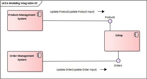
For example, the Eshop system in the following diagram exposes its services through two interfaces, Products and Orders.
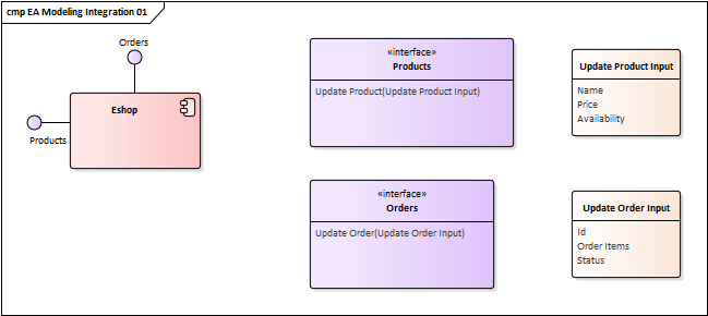
(Interface context menu -> Features & Properties -> Operations)
Interface itself is not connected with the system in any way unless it is modeled as an exposed interface:
- Drag the Expose Interface element from the Component diagram toolbox and drop it on the selected system component in the diagram
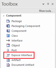
- Choose the interface in the displayed dialog
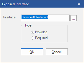
The services are now exposed by the system through the selected interface and could be used for further modeling.
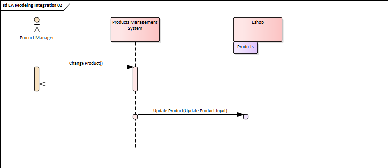
Calling Services in Sequence Diagrams
By default, it is possible to call only operations owned by the lifeline. To call the operations of the exposed interfaces, drag the component into the sequence diagram and select the interfaces from the dialog asking for the "structural elements". Operations of these interfaces will be then included in the list of callable system operations:
Service Calls Without Ordering
Sequence diagrams are great for showing the order in which the services are called. But there are cases when the order is not important, and all that is needed is just to indicate the most important integrations. One possibility is using a communication diagram:
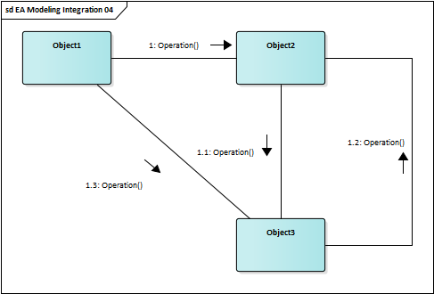
Communication diagrams implicitly show the order of the calls, but it could be suppressed by hiding the numbered labels: Diagram Properties -> Connectors -> Show Collaboration Numbers. This will make the diagram more overview-like, depicting just what services are called without focusing on the order:
Adding new messages: Link context menu -> Add messages from…
II) Batch Files Exchange
In addition to "online" message exchange, file exchange is a common way of integrating systems. It is typically used for big data processing, complex calculations, or sending batch emails, for instance. A convenient way to model batch files exchange, or any flow of data between systems or their components, is using an information flow relationship:
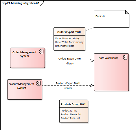
According to the above model, both Order Management System and Product Management System send a data file to the Data Warehouse. The great thing about information flows in EA is that it could be associated with the element representing the data file being transmitted. To add the data file to the relationship, right-click the information flow relationship and select Advanced -> Information Items Conveyed. Then it is possible to navigate from the relationship to the data file using Find Items Conveyed in the relationship context menu.
Note: The two data files are included in the diagram just for illustration. They are associated with the relationship using the Information Items Conveyed and do not need to be included in the diagram.
Specifying Function
Moving on from the "integration level" to the "system level", one of the most important aspects of the system are functions. As with services, it must be clear what is the goal of the function, what are the accepted inputs, and what output it produces, if any. However, functions are usually not modeled as black boxes, so they are specified in a form that allows developers to implement them, including the details such as from which database the data is retrieved or how exactly the algorithm should work.
Effective Analysis models functions the same way as services - through operations. But in contrast to services, functions are internal system components that are not visible to the external systems, so they are not part of the interface. Instead, they are modeled directly as operations of the component representing the system:
According to what is the goal of the function, the description of its internal working may differ:
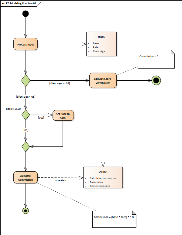
1. Calculations
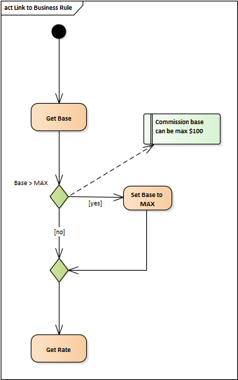
A calculation is basically an algorithm, which expects some data as input, does the calculation, and returns some data as output. The calculation itself does not load any data, so it does not access the database and does not call other functions or services. All data must be provided at the beginning of the function execution. The core benefit of the model is not where to get data, but how the result is calculated.
The following diagram describes the algorithm for calculating commission using the activity diagram:
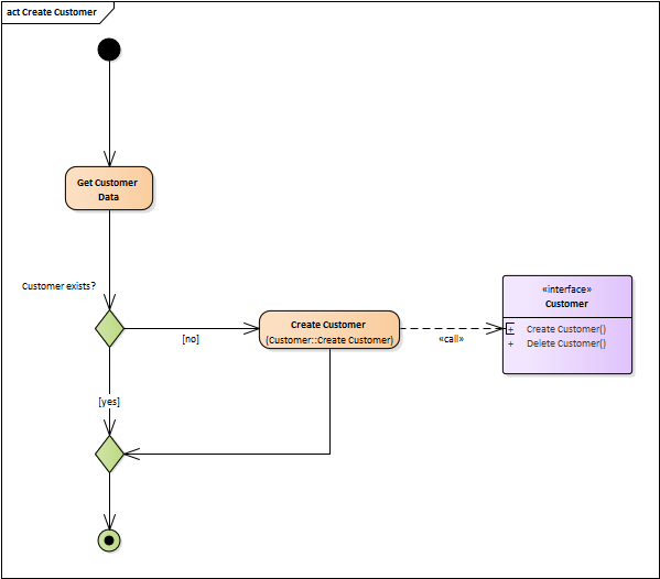
2. Calling Other Functions or Services
Disregarding simple calculations, the goal of most functions is to manipulate data. So analysts must be able to specify what data is loaded, where it comes from, and where the result is stored.
The following example uses an activity diagram to model the internal function Create Customer which processes the loaded customer data and calls an external service to store the customer in the CRM system:
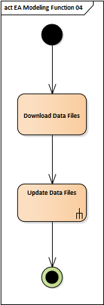
3. Function Decomposition - Activity
It may be tricky for the complex functions to keep the activity diagrams concise, as they may easily break the rule 7 to 9 elements per diagram. If the function is more complex than this, it should be decomposed into subfunctions to keep the diagram readable. In the case of the activity diagram, the subfunction could be modeled using a Composite Structure Diagram:
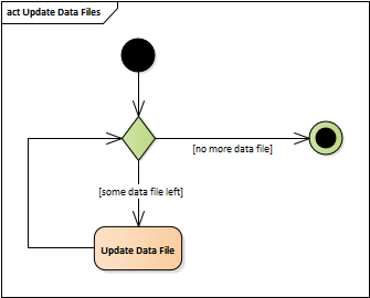
In EA right-click the activity and from the context menu select New Child Diagram -> Composite Structure Diagram. EA will create a new activity diagram for the selected activity and marks the activity with the ∞ symbol. It is then possible to navigate to the subordinate diagram just by double-clicking the element. It is also possible to select an existing composite diagram
4. Function Decomposition - Operation
The same "keep it simple" principle also applies to functions that are described using sequence diagrams. If the diagram is too complex, the function should be decomposed into subfunctions.
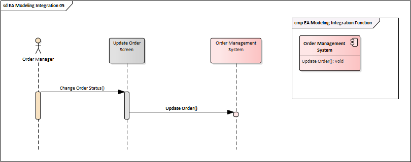
In the following diagram, the employee performs client onboarding using the Onboard Customer Screen. After completing it, she submits the form which triggers the Save Customer() function:
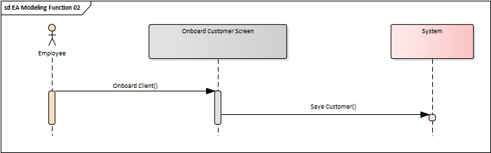
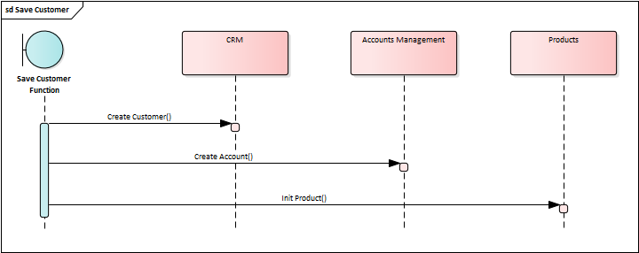
This function then takes care of all activities needed for the successful initialization of the customer: it creates the customer in the CRM, opens an account, and initializes the requested product. The following sequence diagram depicts the decomposition of the Save Customer() function:
The next step is to indicate that the sequence diagram above is a specification of the Save Customer() operation. In the UML terminology, it must be mapped as its behavior:
- Put the diagram into an Interaction (you will find the interaction element in the sequence diagram toolbox under Additional)
- Specify this interaction as the operation's behavior (Operation -> Behavior tab -> Element)
Now we have operation representing the Save Customer() system function and the diagram specifying its behavior. What we need now is an easy way to navigate from the function to its specification (behavior). Unfortunately, there is no easy way to navigate from the operation to its behavior in EA, but it can be done using a third-party extension called EA Navigator. With this extension installed, click the operation in the diagram and select Extensions -> Navigate -> Implementation from the context menu.
Entity State
Each entity includes a set of attributes that describes its characteristics. The entity state is basically just one of the attributes. However, since states may control many aspects of the final system, it is usually worth looking at them from several perspectives.
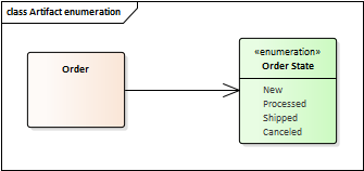
From the data modeling point of view, the entity state is just a static attribute that takes value from the fixed set of items. This is best represented as an enumeration:
Next, most state changes will be reflected in the system as the system must be prepared to react to those changes. For this reason, the person who is responsible for the analysis of the system must understand how the entity state could change because these changes could introduce additional features or constraints to the system.
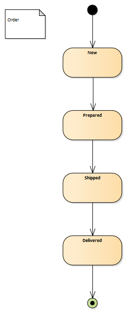
States are modeled using a State Machine Diagram:
And the last important aspect of state modeling is understanding when, where, how, and by whom the state can actually be changed. The trigger could be some business event, when talking about domain entities, or a system event, such as calling a system function if we are considering just entities managed by the system.
Following diagram shows how the business process steps change the state of the order:
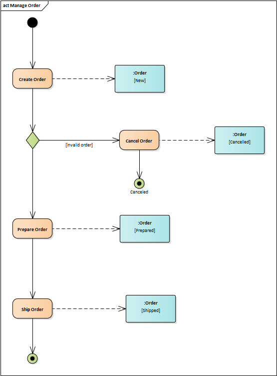
To include entity states in the diagram, follow these steps:
- Place the states right under the modeled entity in the elements tree:
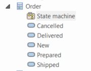
- Drag the entity into the diagram and select it to be inserted as an instance
- Select the inserted instance and choose the state this instance represents by clicking Advanced -> Set Object State in the context menu