Enterprise Architect
The aim of this chapter is to demonstrate how Enterprise Architect can help implement the Effective Analysis principles related to storing information in the unified repository. We will also show how to model various enterprise components along with the tips to increase the productivity of using the tool.
Note: Upcoming chapters assume that the reader has Enterprise Architect installed and has a basic knowledge of the tool. This video tutorial can help with both.
Modeling Tool
Although many teams use Enterprise Architect only to draw UML or other diagrams, it must be emphasized that Enterprise Architect is a modeling tool, not just a drawing tool. The result of "drawing" diagrams in Enterprise Architect is not just a picture, but a model. This means that the user must keep in mind that by inserting a new element in the diagram, a new object representing the element is added to the repository. Similarly, by connecting two elements with a dashed line, the connection is created in the database, and it gets a concrete semantics according to the modeling notation used. In UML, for example, it means that there is a kind of dependency between the two elements connected with the line. So unlike diagramming tools such as Visio, when creating a diagram in CASE, authors must understand the semantics of what they are drawing.
When the author selects to use a standard modeling notation but fails to understand its semantics, it results in diagrams which are not understandable as illustrated by the following examples.
Antipattern #1
In the following model, the analyst wanted to depict that the system first loads invoice data from the database and then it generates invoice documents from the data:
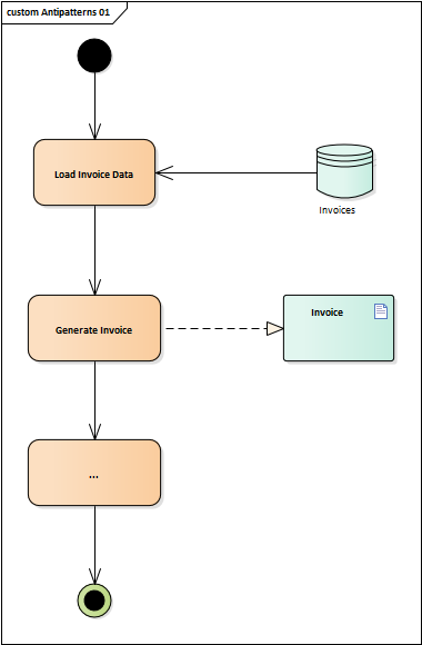
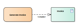
Although the diagram is semantically correct, it does not represent what the author intended to express. The semantics of the used association is not to "create something", so readers can only guess the real meaning. Instead, to describe the fact that something is created, a "create" dependency relationship could be used to indicate that the activity produces invoice:
Note: The summary of UML relationships could be found in this chapter.
Antipattern #2
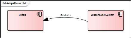
In the second example, the author wanted to describe there is data exchanged between the systems:
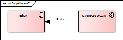
But the arrowed UML line does not mean that some data is coming from Warehouse System to Eshop. There are two possible ways to correct it.
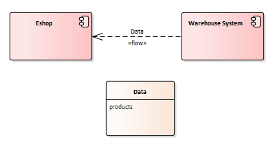
The first approach is to use UML information flow relationship, which can also show the structure of the data being exchanged:
The second possibility is to use the data flow diagram. Unlike the UML alternative, the data flow diagram depicts only the high-level information flow without specifying the structure of the exchanged information:
Enterprise Architect Effectivity Tips
This section presents a couple of useful tips which might be handy for modeling using Enterprise Architect:
- Press
F2to rename the item, both in the project browser or in the diagram - Make the diagrams look cleaner by using line style 'Tree style' or 'Lateral' (line context menu -> Line Style)
- If you need to bend the line strictly according to your needs, use 'Custom line' and bend it using
Ctrl+Q - Quickly locate the selected element in the project browser with
Alt+G - Before deleting an element, make sure it is not used in another diagram using
Ctrl+U - Also, make sure that no other elements are included under the element to be deleted. You can check it by expanding the element in the project browser.
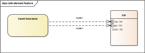
- Sometimes it is useful to create a relationship between element attributes, not just between the elements. To do it, create a relationship between two elements, select the line at one of its ends and in the context menu select 'Link to Element Feature'
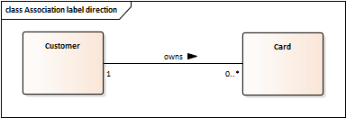
- It is a good practice to name the association between entities and also indicate the direction. This can be done through setting "Direction" in the context menu of the association name:
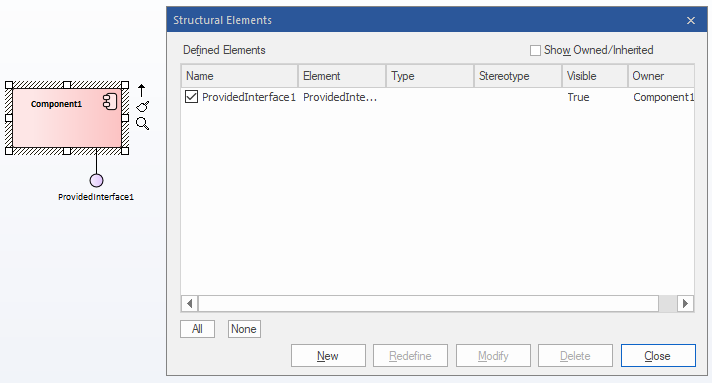
- To hide interfaces provided by a component, unselect them in the "component context menu -> Structural Elements…"
- To hide operation brackets for operation without parameters:
- Diagram properties -> Features Tab -> "Suppress brackets for operations without parameters"
- To hide visibility of class attributes:
- Diagram properties -> Features Tab -> "Show Qualifiers and Visibility Indicators"
- To hide data types of the entities, for example when modeling a domain or logical data model using class diagram:
- Diagram properties -> Features Tab -> "Show Attribute Detail" -> "Name Only"
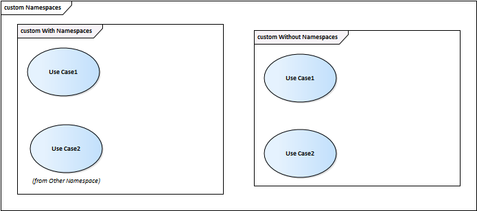
- To supress displaying the element location, use "Diagram context menu -> Properties -> Show Namespace"
- Searching is case sensitive