Entity–Relationship Diagram
Although an ER diagram can be used for both conceptual and logical data modeling, in the "UML era" it is rare to see a domain modeled using an ERD. Where ERDs remain highly popular is in database modeling. What UML Class Diagrams are to the object-oriented world, ERDs are to the world of relational databases.
There are multiple ERD notations; the following picture uses the "Crow's Foot / Martin / Information Engineering style," which is the most common in software engineering:
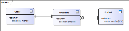
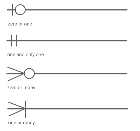
Since ERD diagrams are used for modeling real databases, the entities in the previous diagram are the actual database tables along with their columns, modeled exactly how they were created in the real database. The model can even contain constraints such as primary keys and others. The visualization of entities and their attributes is very similar to a class diagram; what differs is the representation of relationships:
Note: ER models are usually created for a specific database system, such as Oracle DB or MySQL, so they can be vendor-specific. For example, data types or constraints might differ for various database types.